


More about How to Wire Dimmer Switches |
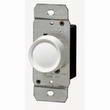
Replacing a Switch with a Dimmer Switch
Hi i'm trying to wire in a dimmer switch. Recent Questions and Posts
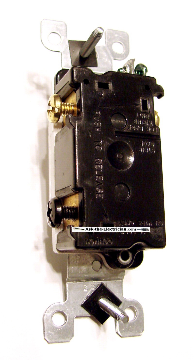
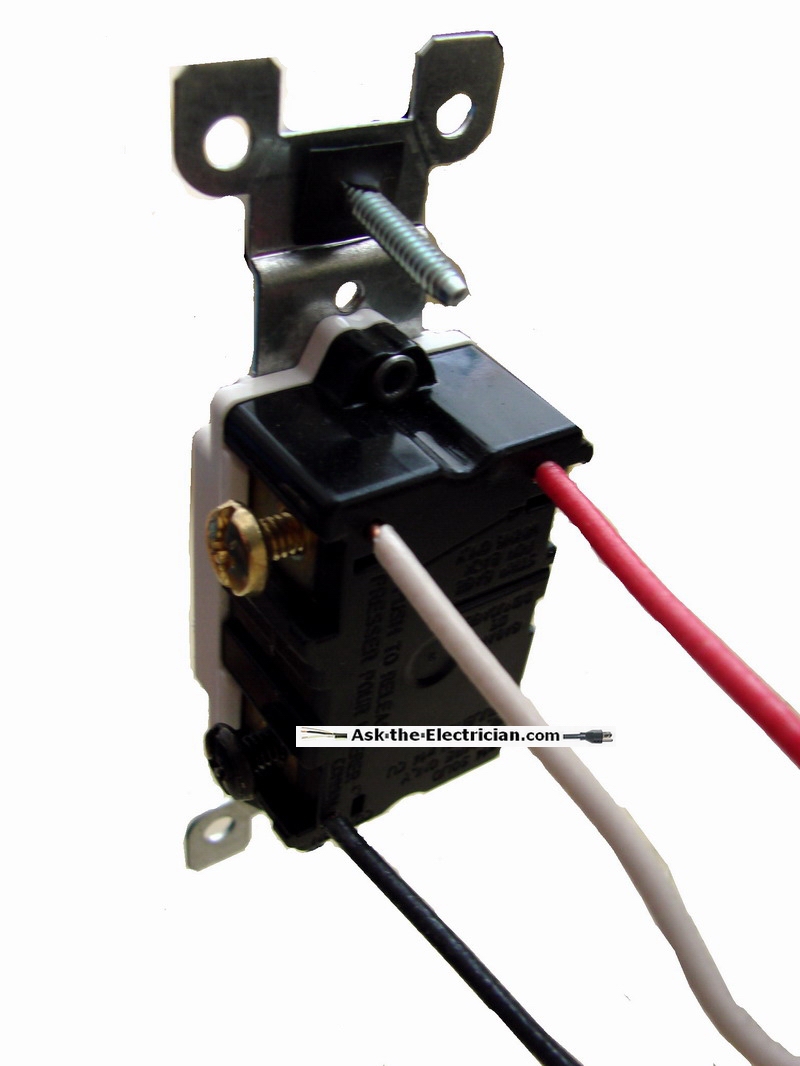
What is causing my light fixtures to be dim? How to Identify and Fix the Cause of Dim Lights, which may be a Indication of an Electrical Problem. How to Check Electric Circuit Wiring causing Dim Lights. How to Wire Ceiling Fan Switches – Step-by-step pictures – Easy wiring diagrams and installation guide – Light and fan switch variations. I just changed a light switch and lost power to my outlets, what did I do wrong? How to Check Light Switch Wiring Connections, Common Light Switch Wiring Problem and Solution. How do I Replace a Switch with a Dimmer Switch for my Light Fixtures? Dimmer Switch Wiring Connections for Light Fixtures. How are 3-way switches wired? The Key to Wiring 3 Way Switch and 3 Way Dimmer Switch Wiring, Key Wiring Configurations for 3 way Switch Wiring. Wiring a Dimmer Switch Wiring for Light Fixtures: Basic Wiring for Light Switches and Dimmers, Identify Switch Box Wires. How to Wire 3Way Dimmer Switches: Common 3Way Dimmer Switch Wire Connections and Light Level Adjustments, Wiring Two 3Way Dimmer Switches. I have a 6 year old who is terrified to walk down the dark hallway at night to get to the bathroom. I wanted to switch out the 3-way switch for a 3-way dimmer switch so I can leave the light on but dimmed so the whole hallway is illuminated. I want to install a dimmer switch in my kitchen. My Electrical box has a switch with one black wire one red wire going to same side of switch. How to Wire a Dimmer Switch: Dimmer Switch Wiring, Dimmer switch wiring diagrams, Wiring a 3-way dimmer switch. |


