


Rewired Home Now Has Issues with Jenn Air StoveMyra, from Delray Beach, Florida asks: A few months ago our 5 yr old electric flat glass top Jenn Air stovetop popped and sparked thru the space around one of the knobs. After it blew, the stovetop stopped working so I turned off the breaker in the fuse box and discovered that several ceiling fans, lights in other rooms in throughout house stopped working as well. We have also noticed on occasion that the fans and lights will just turn on for no reason for various amounts of time as we have left switches on. The house was rewired after it was destroyed by a hurricane 5 years ago. We didn't get much from our insurance company and had to use electricians that were not really great. We have no money right now. First, is there a fire hazard? Second, could it just be a fuse issue and should we try changing them? Please advise. Thank you! Myra, What I would strongly suggest is that you have a qualified licensed electrician perform a series of inspections and tests on the electrical system of the home. What you are experiencing is not normal. It may be that there is another electrical panel which would explain why multiple devices are off when you turned off the circuit breaker. There is a good possibility that a voltage feedback is occurring due to a intermittent or lost connection with a 240 volt circuit which could be verified and repaired by the electrician. Wiring for a 30 Amp 4-Wire Dryer CircuitNelson, from Vivian, Louisiana asks: Dave, in changing a 3 wire dryer outlet to a 4 wire using a 10-4 circuit, what does the connection in the breaker panel look like. Appreciate your answer, Nelson Nelson, The connections for the dryer circuit in a main electrical panel are the two power conductors commonly the black and the red to the 2-pole 30 amp circuit breaker, and the white neutral and the ground attach to the bonded neutral terminal bar. If the circuit wiring has been installed at a sub-panel then the white neutral attaches to the neutral terminal bar, and the ground attached to the ground terminal bar. Please be aware that I recommend that wiring and connections in any electrical panel should be done by a licensed electrician. More about Circuit Breaker Panels
Learn more about Circuit Breaker Panel |
» Home Electrical Wiring
» Electrical Wiring Directory
» Circuit Breakers and Fuses
» Need Electrical Help? Ask the Electrician
» Circuit Breakers and Fuses
» Need Electrical Help? Ask the Electrician
Home Circuit Breaker Panel

|
Summary: The home circuit breaker panel contains several circuit breakers that are carefully installed by experienced electricians and electrical contractors.
© By: Dave Rongey |
How Circuit Breakers are Installed Into a Panel
Each manufacturer of circuit breaker panels has its own unique design and layout containing terminals strips for attaching the neutral wire conductors and the ground system that is bonded to the panel and the entire home electrical system. The circuit breaker panel also contains the metal contact surfaces that make connection to the circuit breakers that are installed into the electrical panel. These metal components are also known as the panel bus assembly.
The Circuit Breaker and the Panel Assembly |
|
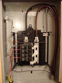 |
The Sub Panel This series of photos show a 100 amp circuit breaker sub-panel. The most revealing factor is that the neutral wire conductor and the bonded ground wire are located in separate lugs and terminal strips. The only location where the neutral and ground wires are actually bonded are at the main electrical panel. Notice how the metal bus assembly has exposed parts in the center area where the circuit breakers are connected to. The panel bus assembly is energized with live electrical, power whenever the main panel circuit breaker is in the on position. Each circuit breaker panel has its own unique characteristics which an experienced electrician is familiar with. Homeowners or do-it-yourself ers should not perform any work in any electrical circuit breaker panel. |
 |
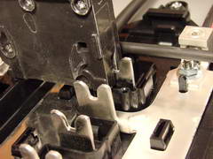
The Breaker Connection with the Panel The buss of this particular circuit breaker panel is arraigned so that two columns of circuit breakers may be installed back-to-back. This photo shows how the metal contact surfaces of this circuit breaker makes contact with the panel buss by sliding down over each side of the centrally located metal bus. This creates a good connection with the panel bus and enables electricity to pass from the panel bus into the internal parts of the circuit breaker. |
 |
The Installation of a Circuit Breaker The circuit breaker has been installed using the black plastic side rail of the panel assembly. When the circuit breaker is installed correctly it will be noticeably level or line up evenly compared to other circuit breakers. If a circuit breaker appears to be uneven or not level then the circuit breaker may no have been installed correctly. |
 |
The Panel Bus Assembly This photo shows how the circuit breaker is fully seated into place with the panel bus and the same bus is available for another circuit breaker to be installed on the opposite side of the panel. The first circuit breaker is possibly the one that could be installed out of alignment because it does not have any other breakers to serve as a reference or guide. |
 |
The Side Mounting Rail of the Panel This photo shows the side rail of the circuit breaker panel which has a clip which is designed to line up with the end of the circuit breaker and serve as fastener for the side of the circuit breaker. If the circuit breaker does not slide into the side rail clip then the side of the circuit breaker will appear high and uneven, and the circuit breaker will not be installed correctly. Shown here is the brass screw terminal where the circuit wire conductor will be attached and securely fastened. |
More about Circuit Breaker Panels |
|
Question: I have two wires coming from breaker panel I need to run a porch light and two room lights plus ceiling fans.
Answer: Bud, you stated that the wires were the Red, Black, White wires, if so did you run 2 separate circuits, or just one? Because you really only need one circuit for this type of load. I'm also assuming you also have a Ground Wire. NOTE: This question is based on a specific project. Ask The Electrician provides help for your electrical project: Ask Electrical Questions |

|


