


» Filed under: Electrical Wiring
» Need Help? Get a Quick Reply! Electrical Help with Your Project
Home Electrical Wiring Safety

|
Electrical Wiring Tips and Safety Advice about Home Electrical Wiring Projects and Electrical Repairs – All Home Electrical Wiring projects should be planned out to avoid mistakes which is outlined in this guide and throughout this website. © By: Dave Rongey |
Electrical Wiring VideoHome Electrical Wiring TipsHome Electrical Wiring TipsCheck out my YouTube Channel:AskTheElectrician - Electrical Tips and Be Sure to Subscribe! |
|
|
Electrical Wiring Resource that Helps You Avoid Mistakes
Electrical Question: Yesterday we installed a new hot water heater in a house that’s 60-70 years old, and we decided to replace the electrical wiring because it looked old and rough.
- When adding the electrical wiring, I did something that cause huge sparks and melted my screwdriver, and I don’t know what I did. I’ll explain
- The circuit breaker was in the open position, with both 30 amp fuses removed. I cut the wire at the tank, so I know for sure it was dead at that point. Then I removed the existing wiring from the box.
- I ran my new yellow wire into the top of the box, and then ran the ground up to the existing ground from the panel box next to it.
- Then I was installing the black wire to the bottom screw, trying to push my hooked wire end above the screw so I could slide it under it. I pushed the hooked end up into the slot in the fuse threads to get it to slide back under the screw.
- My screwdriver made contact with the bar of the knife switches, and melted my screwdriver and threw out a blast of sparks.
- I don’t understand why this happened being that both fuses were removed, and the breaker was in the open position. I only touched below the fuses with my screwdriver.
- On the right side of the knife switch bar, you can see the groove of melted steel. Notice the burnt white wire on the right side of the box.
This electrical question came from: Steeler, a Homeowner from Providence, Rhode Island.
Dave’s Reply:
Thanks for your electrical question Steeler.
Home Electrical Wiring Safety Is Essential
Safety with Home Electrical Wiring Projects and Electrical Repairs Is Essential
- Steeler, an electric spark or an electric arc flash can result from a direct short to ground or it may occur when a completed circuit takes place and there is an electrical load.
- What you are describing could have been due to any number of reasons, but I will venture to say that it is due to your lack of experience of knowing exactly what you are doing.
- This is one of the causes for electrical problems that can lead to circuit failures and even injury.
ELECTRICAL SAFETY NOTE: Please – If you do not fully understand what you are doing, then call a Professional Licensed Electrical Contractor.
The Following will assist you with your Electrical Wiring:
FREE Electrical Wiring eBook and Safety Advice about Home Electrical Wiring Projects and Electrical Repairs.
All home electrical wiring projects should be planned out to avoid mistakes which is outlined in this eBook and throughout this website.
How To Avoid Electrical Wiring Mistakes

Home Electrical Safety Articles
Electrical Safety
Electrical Safety Articles covering several topics of home electrical safety and Do-It-Yourself Electrical Safety.

Home Electrical Safety
A new approach to keep kids and electricity apart with hopes to prevent children from being injured by electricity.

The following may also be helpful for you:
|
|

Be Careful and Be Safe - Never Work on Energized Circuits!
Consult your Local Building Department about Permits and Inspections for all Electric Wiring Projects.
The Safest Way to Test Electrical Devices and Identify Electric Wires!The Non-Contact Electrical TesterThis is a testing tool that I have had in my personal electrical tool pouch for years, and is the first test tool I grab to help identify electrical wiring. It is a Non-contact tester that I use to easily Detect Voltage in Cables, Cords, Circuit Breakers, Lighting Fixtures, Switches, Outlets and Wires. Simply insert the end of the tester into an outlet, lamp socket, or hold the end of the tester against the wire you wish to test. Very handy and easy to use.
The Quickest Way to Check for Faulty Electrical Wiring!The Plug-In Outlet TesterThis is the first tool I grab to troubleshoot a problem with outlet circuit wiring. This popular tester is also used by most inspectors to test for power and check the polarity of circuit wiring. It detects probable improper wiring conditions in standard 110-125 VAC outlets Provides 6 probable wiring conditions that are quick and easy to read for ultimate efficiency Lights indicate if wiring is correct and indicator light chart is included Tests standard 3-wire outlets UL Listed Light indicates if wiring is incorrect Very handy and easy to use.
Strip Off Wire Insulation without Nicking and Damaging the Electric Wire!The Wire Stripper and Wire CutterMy absolute favorite wire stripping tool that I have had in my personal electrical tool pouch for years, and this is the tool I use to safely strip electrical wires. This handy tool has multiple uses: The wire gauges are shown on the side of the tool so you know which slot to use for stripping insulation. The end of the tool can be used to grip and bend wire which is handy for attaching wire onto the screw terminals of switches and outlets.. The wire stripper will work on both solid and stranded wire. This tool is Very Handy and Easy to Use. |
||
Electrical Parts to Help You Wire it Right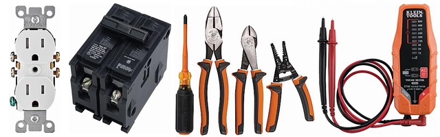
Residential Electrical Parts and AccessoriesLight Switches 120volt Outlets Circuit Breakers Electrician Tools Voltage Testers | ||


|
Installing Electrical Wiring
Thank you very much in advance. This electrical wiring project came from: Slava, a Homeowner from Brooklyn, New York. Electrical Project #2:
This electrical wiring question came from Sue in West Linn, Oregon Dave’s Reply: Home Electrical Wiring TechniquesApplication: Installing Additional Electrical Wiring. Basic Fundamentals of Home Electrical WiringObtaining knowledge before starting a home electrical wiring project is very wise. The information below will describe how to avoid hitting an electrical wire and causing damage. Basic Methods of Home Electrical Circuit Wiring
The NEC addresses Un-Supported Cables inside Existing WallsRE: NEC 334.30 section (B)
More about Home Electric Wiring
|


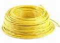
| Electrical wiring diagrams that are in color have an advantage over ones that are black and white only. *The individual wires on the diagram should be colored the same as the actual wires you will be using. Green or bare wire is the ground wire. White or off-white is neutral. The neutral wire carries power back to the service panel. Black indicates the hot wire. The hot wire carries power from the panel to the device you are wiring. Red blue, or other colors also indicate hot wires. |
 See more about the types of wire and what they are used for. More about wire See more about the types of wire and what they are used for. More about wire
*Important Note: When wires or cables such as Romex are used with switching applications and as Switch Legs, the function of a colored wire may be different from what is noted here. The only way to positively identify wires used for any application is to purchase a good volt tester and understand how to use it. |
Electrical Wiring Symbols
When looking at any wiring diagram, start by familiarizing yourself with the symbols that are being used.
The electrical symbols will not only show where something is to be installed, but what type of device is being installed.
Make sure you understand the symbols on your diagram before beginning your project. There should be a chart on your diagram showing what the different symbols being used represent, much like a legend on a map.
 |
A surface ceiling light will be shown by one symbol, a recessed ceiling light will have a different symbol, and a surface fluorescent light will have another symbol. Each type of switch will have a different symbol and so will the various outlets. You’ll even find symbols showing the location of smoke detectors, your doorbell chime, and the thermostat. Click on the link to find out more about the different electrical wiring diagram symbols |
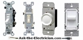
Light Switches
When it comes to household electricity, there’s a lot more to consider than simply turning a switch On or Off. Some of the most common questions electricians receive involve switches. Once you understand the different types of switches and follow a good wiring diagram, you should be able to install a new switch in your home or repair existing problems with the ones you have.
Here are some of the more common switching configurations.
After absorbing the following information, you will be able to wire switches just as well as the pros:
| Single-Pole Switches A Single-Pole Switch provides switching from one location only. Single-Pole may sound simple, but there are different ways to wire a Single-Pole Switch. The power can come from either the switch box or the fixture box and a set of electrical wiring diagrams will explain each of these scenarios to you clearly. |
 |
 |
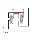
3-Way Switches 3-Way Switches are used to control one or more fixtures from two different locations. This is a common configuration in hallways and staircases. There are many ways to wire a 3-Way Switch. The power can start at a fixture or either of the two switches. Without a wiring diagram it can be very easy to make a serious mistake that will cause the circuit to malfunction and possibly become a hazard. |
 |
Dimmer Switches A wiring diagram will even take the mystery out of wiring a 3-Way Dimmer Switch A dimmer switch can be either a rotary or a sliding switch that lets you adjust the intensity of a light. Both are wired the same way. What a great way to enjoy softer light and a reduced energy bill! |
 |
| 4-Way Switches
One of the most complicated wiring configurations is a |
 |
 |
Safety when Wiring Switches As important as electrical wiring diagrams are to the successful completion of your wiring project, safety and respect for electricity are essential. Never work on live circuits. Before you begin your project, identify the circuit you’re working on and then turn off power to that circuit at the main panel. Then confirm that the power is off with a voltage tester. IMPORTANT:If at any time you feel unsure about what you’re doing, please call a licensed electrical contractor. |
More about Wiring Light Switches
Single Pole Switches
Wiring diagrams that explain the basic wiring for lighting control from a single switch location.
3-Way Switches
Once you see these wiring diagrams you will understand how to wire 3-way switches.
3-Way Dimmer Switches
Take the mystery out of wiring a 3-way dimmer switch and enjoy softer light and a reduced energy bill when you use one of these wiring diagrams.
4-Way Switches
Did you know – you can have any number of these switches installed on one control circuit? Once you see how these switches are wired you’ll be amazed, its just one more step up from the 3-way design – you have to see these wiring-diagrams!
Resources to help you with Home Wiring
Electrical Wiring Outlets for the Home
110 Volt Outlets
220 Volt Outlets
Residential Wiring Diagrams
More about Home Electrical
Home Electrical Wiring for Bathrooms
Home Electrical Wiring for Bedrooms
Home Electrical Wiring for Kitchens
Home Electrical Wiring for Home Office
Home Electrical Wiring for Laundry Room
Home Electrical Wiring for Garages
Home Electrical Wiring for Workshops
Home Electrical Wiring Diagrams for Outlets
Electrical Wiring Diagram Symbols
Ask The Electrician – Main page
Home Wiring Diagrams
Wiring diagrams can be helpful in many ways, including illustrating wire colors, showing where different elements of your project go using electrical symbols, and showing what wire goes where. This is why a good wiring diagram is important for wiring your home safely.
Keep your wiring diagrams nearby. You’ll want to refer to them often as you work on your project.
| Electrical wiring diagrams that are in color have an advantage over ones that are black and white only. *The individual wires on the diagram should be colored the same as the actual wires you will be using. Green or bare wire is the ground wire. White or off-white is neutral. The neutral wire carries power back to the service panel. Black indicates the hot wire. The hot wire carries power from the panel to the device you are wiring. Red blue, or other colors also indicate hot wires. |
See more about the types of wire and what they are used for. More about wire
*Important Note: When wires or cables such as Romex are used with switching applications and as Switch Legs, the function of a colored wire may be different from what is noted here. The only way to positively identify wires used for any application is to purchase a good volt tester and understand how to use it. |
Electrical Wiring Symbols
When looking at any wiring diagram, start by familiarizing yourself with the symbols that are being used.
The electrical symbols will not only show where something is to be installed, but what type of device is being installed.
Make sure you understand the symbols on your diagram before beginning your project. There should be a chart on your diagram showing what the different symbols being used represent, much like a legend on a map.
|
A surface ceiling light will be shown by one symbol, a recessed ceiling light will have a different symbol, and a surface fluorescent light will have another symbol. Each type of switch will have a different symbol and so will the various outlets. You’ll even find symbols showing the location of smoke detectors, your doorbell chime, and the thermostat. Click on the link to find out more about the different electrical wiring diagram symbols |
Light Switches
When it comes to household electricity, there’s a lot more to consider than simply turning a switch On or Off. Some of the most common questions electricians receive involve switches. Once you understand the different types of switches and follow a good wiring diagram, you should be able to install a new switch in your home or repair existing problems with the ones you have.
Here are some of the more common switching configurations.
After absorbing the following information, you will be able to wire switches just as well as the pros:
| Single-Pole Switches A Single-Pole Switch provides switching from one location only. Single-Pole may sound simple, but there are different ways to wire a Single-Pole Switch. The power can come from either the switch box or the fixture box and a set of electrical wiring diagrams will explain each of these scenarios to you clearly. |
|
|
3-Way Switches 3-Way Switches are used to control one or more fixtures from two different locations. This is a common configuration in hallways and staircases. There are many ways to wire a 3-Way Switch. The power can start at a fixture or either of the two switches. Without a wiring diagram it can be very easy to make a serious mistake that will cause the circuit to malfunction and possibly become a hazard. |
|
Dimmer Switches A wiring diagram will even take the mystery out of wiring a 3-Way Dimmer Switch A dimmer switch can be either a rotary or a sliding switch that lets you adjust the intensity of a light. Both are wired the same way. What a great way to enjoy softer light and a reduced energy bill! |
|
| 4-Way Switches
One of the most complicated wiring configurations is a |
|
|
Safety when Wiring Switches As important as electrical wiring diagrams are to the successful completion of your wiring project, safety and respect for electricity are essential. Never work on live circuits. Before you begin your project, identify the circuit you’re working on and then turn off power to that circuit at the main panel. Then confirm that the power is off with a voltage tester. IMPORTANT:If at any time you feel unsure about what you’re doing, please call a licensed electrical contractor. |
More about Wiring Light Switches
Single Pole Switches
Wiring diagrams that explain the basic wiring for lighting control from a single switch location.
3-Way Switches
Once you see these wiring diagrams you will understand how to wire 3-way switches.
3-Way Dimmer Switches
Take the mystery out of wiring a 3-way dimmer switch and enjoy softer light and a reduced energy bill when you use one of these wiring diagrams.
4-Way Switches
Did you know – you can have any number of these switches installed on one control circuit? Once you see how these switches are wired you’ll be amazed, its just one more step up from the 3-way design – you have to see these wiring-diagrams!
Resources to help you with Home Wiring
Electrical Wiring Outlets for the Home
110 Volt Outlets
220 Volt Outlets
Residential Wiring Diagrams
More about Home Electrical
Home Electrical Wiring for Bathrooms
Home Electrical Wiring for Bedrooms
Home Electrical Wiring for Kitchens
Home Electrical Wiring for Home Office
Home Electrical Wiring for Laundry Room
Home Electrical Wiring for Garages
Home Electrical Wiring for Workshops
Home Electrical Wiring Diagrams for Outlets
Electrical Wiring Diagram Symbols
Ask The Electrician – Main page
Residential Electric Panel
Electrical Question: How should I upgrade my electric service panel?
Our home was built in 30’s. The service meter is 200amps. The panel originally installed is an old Square D. The problem is there are several circuits bundled together and terminated under breaker lugs. The service entrance wire from the meter to the panel is two insulated 2/0 aluminum wires and one aluminum stranded twisted around both the others. The entire service wire is in a sheath covered cable. There is a solid number 4 copper ground coming from the exterior ground rod to the existing panel. There is no visible insulated neutral wire (Typically seen in older homes). We want to change out the panel and install a new 200 amp main panel.
My questions are:
- Is it safe, being I have a solid ground to take the single strand wire and twist it together, coat it with insulation electrical tape not to have any bare wire existing, and use it as a neutral wire? The existing wire was installed when walls were open and is strapped. We will have to tear out a wall cavity to replace it, which is what I want to avoid if possible.
- Second, What is the farthest distance allowed from the meter can to the location of a panel with main? I will consider running copper as feed. Third, If replacement is our only choice for the entrance wire, will the meter head can have to be changed also?
Additional Comments: Great website.
This electrical question came from ML, a Homeowner in North Carolina.
Dave’s Reply:
Thanks for your electrical question.
Upgrading an Electric Service Panel
Application: Upgrading a Residential Electrical Service Panel.
Skill Level: Advanced – Not recommended for homeowners, This project is best performed by a Licensed Electrical Contractor, or Certified Electrician.
Electrical Tools Required: Basic Electricians Pouch Hand Tools, Voltage Tester, and appropriate Safety Gear.
Estimated Time: Depends on the personal level experience, ability to work with tools, install electrical circuit wiring, and the available access to the project area.
Electrical Safety: Identify the electrical power source to the Main Panel, turn it OFF and Tag with a Note before working with the electrical wiring.
Electrical Wiring Parts and Materials: Electrical parts and materials for the Main Panel should be approved for the specific project and compliant with local and national electrical codes.
Electrical Codes and Inspections: Installing or changing home electrical wiring should be done according to local and national electrical codes as adopted in your local area. A permit and inspections may also be required.
Main Electrical Service Panel
- Be aware that at the main electrical service panel the neutral and ground wires are bonded together. This however is only at the main service panel.
- Additional panels that are added such as a sub panel, are then required to have separate wires for the ground and neutral which will originate and bond together back at the main electric service panel.
- Typically the bonding of the neutral wires and the ground wires is done at the main electrical service where these wires are attached to the terminal block system which is located inside the main electric service panel.
- The service entrance cable that you have described is typical.
- The ground wire system that you have described is also typical as long as it has been installed and bonded properly.
- To correct the problem of having more than one circuit wire attached to a single circuit breaker, you may want to consider installing an additional sub panel where more circuit breakers may be installed.
More about Upgrading an Electric Service Panel
Electrical Codes for Services
Wiring Electrical Codes
House Wiring Circuits and Circuit Breakers
This article looks at common 120 volt and 240 volt house wiring circuits and the circuit breakers that are installed identifying the types and amperage sizes used in most homes.
Electrical Panel Circuit Listing

Electric Circuit Listing
The size of the home electrical service panel is designed by calculating the square footage of the home and factoring in the code requirements for the electrical circuits that are required.
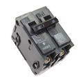
Home Electrical Circuit Breakers
A guide to home electrical circuit breakers and how they work to protect your electrical wiring. When properly installed, your home electrical wiring is protected by a circuit protection device.
Electrical Wire for the Home
Complete listing of electrical wire types and parts used for home projects with electrical code information serves as selection guidelines.

Electrical Grounding Methods and Requirements
Listing of electrical codes for grounding with examples of electrical grounding codes for home electrical wiring.
Residential Electric Panel
Electrical Question: How should I upgrade my electric service panel?
Our home was built in 30’s. The service meter is 200amps. The panel originally installed is an old Square D. The problem is there are several circuits bundled together and terminated under breaker lugs. The service entrance wire from the meter to the panel is two insulated 2/0 aluminum wires and one aluminum stranded twisted around both the others. The entire service wire is in a sheath covered cable. There is a solid number 4 copper ground coming from the exterior ground rod to the existing panel. There is no visible insulated neutral wire (Typically seen in older homes). We want to change out the panel and install a new 200 amp main panel.
My questions are:
- Is it safe, being I have a solid ground to take the single strand wire and twist it together, coat it with insulation electrical tape not to have any bare wire existing, and use it as a neutral wire? The existing wire was installed when walls were open and is strapped. We will have to tear out a wall cavity to replace it, which is what I want to avoid if possible.
- Second, What is the farthest distance allowed from the meter can to the location of a panel with main? I will consider running copper as feed. Third, If replacement is our only choice for the entrance wire, will the meter head can have to be changed also?
Additional Comments: Great website.
This electrical question came from ML, a Homeowner in North Carolina.
Dave’s Reply:
Thanks for your electrical question.
Upgrading an Electric Service Panel
Application: Upgrading a Residential Electrical Service Panel.
Skill Level: Advanced – Not recommended for homeowners, This project is best performed by a Licensed Electrical Contractor, or Certified Electrician.
Electrical Tools Required: Basic Electricians Pouch Hand Tools, Voltage Tester, and appropriate Safety Gear.
Estimated Time: Depends on the personal level experience, ability to work with tools, install electrical circuit wiring, and the available access to the project area.
Electrical Safety: Identify the electrical power source to the Main Panel, turn it OFF and Tag with a Note before working with the electrical wiring.
Electrical Wiring Parts and Materials: Electrical parts and materials for the Main Panel should be approved for the specific project and compliant with local and national electrical codes.
Electrical Codes and Inspections: Installing or changing home electrical wiring should be done according to local and national electrical codes as adopted in your local area. A permit and inspections may also be required.
Main Electrical Service Panel
- Be aware that at the main electrical service panel the neutral and ground wires are bonded together. This however is only at the main service panel.
- Additional panels that are added such as a sub panel, are then required to have separate wires for the ground and neutral which will originate and bond together back at the main electric service panel.
- Typically the bonding of the neutral wires and the ground wires is done at the main electrical service where these wires are attached to the terminal block system which is located inside the main electric service panel.
- The service entrance cable that you have described is typical.
- The ground wire system that you have described is also typical as long as it has been installed and bonded properly.
- To correct the problem of having more than one circuit wire attached to a single circuit breaker, you may want to consider installing an additional sub panel where more circuit breakers may be installed.
More about Upgrading an Electric Service Panel
Electrical Codes for Services
Wiring Electrical Codes
House Wiring Circuits and Circuit Breakers
This article looks at common 120 volt and 240 volt house wiring circuits and the circuit breakers that are installed identifying the types and amperage sizes used in most homes.
Electrical Panel Circuit Listing
Electric Circuit Listing
The size of the home electrical service panel is designed by calculating the square footage of the home and factoring in the code requirements for the electrical circuits that are required.
Home Electrical Circuit Breakers
A guide to home electrical circuit breakers and how they work to protect your electrical wiring. When properly installed, your home electrical wiring is protected by a circuit protection device.
Electrical Wire for the Home
Complete listing of electrical wire types and parts used for home projects with electrical code information serves as selection guidelines.
Electrical Grounding Methods and Requirements
Listing of electrical codes for grounding with examples of electrical grounding codes for home electrical wiring.
Guide to Installing Electrical or Type NM Cable
Electrical Question: Topic: Kinks and bends in Type NM Cable Sheathing.
- Is having a kink or twist in Type NM Cable a hazard?
- I have not had an inspector look at the wiring because I always find inspectors to nit pick about little things.
- Your going to have to bend the wire when it is inside the box anyway?
- I used the right gauge wire with breaker etc., and staple the wire flat to the joist and studs.
- If it is wrong can I fix it by taking the 90 degree angle out or do I have to run new wire?
- I have installed 14 gauge wire with receptacles.
- Someone mentioned to me that bends in the wire can cause a hot spot.
This electrical wiring question came from: Justin, from Wappingers Falls, New York.
Additional Comments: Nice that you care to help others. Thanks!
Dave’s Reply:
Thanks for your electrical wiring question Justin.
How to Install Type NM Type Electrical Cable
Preparation
- Skill Level: Intermediate to Advanced. This electrical wiring project is best performed by a Licensed Electrical Contractor.
- Tools Required: Electricians Pouch of Hand Tools for Rough-In Wiring, Electric Drill and Auger Bits, Extension Cords, and a Ladder as needed.
- Safety: All personal safety measures must be taken when performing remodel projects where you may come into contact with hazardous materials and environmental contaminants such as fiberglass insulation, vermiculite and asbestos, molds or mildew, as well as dust.
- Estimated Time: Depends on the extent of the project, the type of wall coverings and structural construction and available access to the project area.
- Precaution: Any existing electrical wiring in the immediate area that may interfere with the installation should be identified and turned OFF and Tagged.
- Notice: Installing additional electrical wiring or upgrading existing electrical circuits and wiring should always be done according to local and national electrical codes with a permit and be inspected.
Common Practices and Methods for Installing Type NM Cable for Home Electrical Wiring
Beware of Damaged or Defective Electrical Cable
- First, lets make sure that this question is not describing damaged cable, so here is what damaged cable looks like: If the insulation has an irregularity or physical damage then it should not be used. This would include rips or tears in the outside sheathing.
- If the cable has what appears to be a knot inside the cable under the outside sheathing then the cable should not be used. Some of these descriptions may be due to flaws in the manufacturing process which may affect the safety or functionality of the cable.
- The good news is that this hardly ever is a problem with type NM cable that is manufactured by well known companies, however there have been rare occasions where a bad batch of wire was sent out that had inconsistencies.
- If defective cable is installed then it could cause a lot of problems which would most likely require the cable to be removed an replaced. During the past 38 years I have seen only a few times where cable had been defective.
Installing NM Type Cable
- The best way to install NM cable is when the cable is flat which is best accomplished by rolling out the cable like the rolling of a tire or my favorite method is using a stud real which allows the cable to be dispensed from the roll as it is needed.
Electrical Cable Bends and Kinks
- It is best for the cable to be flat, however if the cable has a few twists it will not hurt.
- Flat cable makes for easy installation and stapling.
- The smoother the cable is the easier it is to work with and this makes for a nice neat installation.
- There should not be any loops or kinks when installing NM cable.
- I see people on the internet describe loops and even show diagrams showing large loops of cable even right before the entry into a box and this practice can cause problems when the insulation and wall covering is installed which may create a damaged cable.
IMPORTANT
All electrical wiring projects should be installed with a permit and be inspected by the local building authority.
More about Installing Electrical Wiring and Cable
Electrical Wire for the Home
Complete listing of electrical wire types and parts used for home projects with electrical code information serves as selection guidelines.
Home Electrical Junction Boxes

Electrical Junction Boxes for Home Wiring
Understanding electrical junction boxes and what they are used for. Home electrical wiring is the process of installing electrical wire to a location that will serve electrical devices or an appliance. One very important component is the box where the wire will be installed. The type and size of the home wiring electrical boxes will depend upon the circuit size, application and its location.
Guide to Installing Electrical or Type NM Cable
Electrical Question: Topic: Kinks and bends in Type NM Cable Sheathing.
- Is having a kink or twist in Type NM Cable a hazard?
- I have not had an inspector look at the wiring because I always find inspectors to nit pick about little things.
- Your going to have to bend the wire when it is inside the box anyway?
- I used the right gauge wire with breaker etc., and staple the wire flat to the joist and studs.
- If it is wrong can I fix it by taking the 90 degree angle out or do I have to run new wire?
- I have installed 14 gauge wire with receptacles.
- Someone mentioned to me that bends in the wire can cause a hot spot.
This electrical wiring question came from: Justin, from Wappingers Falls, New York.
Additional Comments: Nice that you care to help others. Thanks!
Dave’s Reply:
Thanks for your electrical wiring question Justin.
How to Install Type NM Type Electrical Cable
Preparation
- Skill Level: Intermediate to Advanced. This electrical wiring project is best performed by a Licensed Electrical Contractor.
- Tools Required: Electricians Pouch of Hand Tools for Rough-In Wiring, Electric Drill and Auger Bits, Extension Cords, and a Ladder as needed.
- Safety: All personal safety measures must be taken when performing remodel projects where you may come into contact with hazardous materials and environmental contaminants such as fiberglass insulation, vermiculite and asbestos, molds or mildew, as well as dust.
- Estimated Time: Depends on the extent of the project, the type of wall coverings and structural construction and available access to the project area.
- Precaution: Any existing electrical wiring in the immediate area that may interfere with the installation should be identified and turned OFF and Tagged.
- Notice: Installing additional electrical wiring or upgrading existing electrical circuits and wiring should always be done according to local and national electrical codes with a permit and be inspected.
Common Practices and Methods for Installing Type NM Cable for Home Electrical Wiring
Beware of Damaged or Defective Electrical Cable
- First, lets make sure that this question is not describing damaged cable, so here is what damaged cable looks like: If the insulation has an irregularity or physical damage then it should not be used. This would include rips or tears in the outside sheathing.
- If the cable has what appears to be a knot inside the cable under the outside sheathing then the cable should not be used. Some of these descriptions may be due to flaws in the manufacturing process which may affect the safety or functionality of the cable.
- The good news is that this hardly ever is a problem with type NM cable that is manufactured by well known companies, however there have been rare occasions where a bad batch of wire was sent out that had inconsistencies.
- If defective cable is installed then it could cause a lot of problems which would most likely require the cable to be removed an replaced. During the past 38 years I have seen only a few times where cable had been defective.
Installing NM Type Cable
- The best way to install NM cable is when the cable is flat which is best accomplished by rolling out the cable like the rolling of a tire or my favorite method is using a stud real which allows the cable to be dispensed from the roll as it is needed.
Electrical Cable Bends and Kinks
- It is best for the cable to be flat, however if the cable has a few twists it will not hurt.
- Flat cable makes for easy installation and stapling.
- The smoother the cable is the easier it is to work with and this makes for a nice neat installation.
- There should not be any loops or kinks when installing NM cable.
- I see people on the internet describe loops and even show diagrams showing large loops of cable even right before the entry into a box and this practice can cause problems when the insulation and wall covering is installed which may create a damaged cable.
IMPORTANT
All electrical wiring projects should be installed with a permit and be inspected by the local building authority.
More about Installing Electrical Wiring and Cable
Electrical Wire for the Home
Complete listing of electrical wire types and parts used for home projects with electrical code information serves as selection guidelines.
Home Electrical Junction Boxes
Electrical Junction Boxes for Home Wiring
Understanding electrical junction boxes and what they are used for. Home electrical wiring is the process of installing electrical wire to a location that will serve electrical devices or an appliance. One very important component is the box where the wire will be installed. The type and size of the home wiring electrical boxes will depend upon the circuit size, application and its location.
Planning Electrical Circuits for a House
Electrical Question: I am working on a custom home building project where we will be installing the electric wiring.
- We have a design layout for all the rooms that has been prepared by an architect.
- The house will have 4 bedrooms and 2 bathrooms. along with a laundry room and kitchen.
- It has not been determined just how many circuits the home will require.
- There will be many electrical appliances in the kitchen, including a dishwasher.
- Is there a minimum number of outlets that must be wired for each room?
- How are overhead light switches wired into the circuit?
Additional Comments: Very helpful.
Background: Michael, from Batron Rouge, LA.
Dave’s Reply:
Thanks for your home wiring question Michael.
Electrical Circuit Wiring for a Home

Application: Electrical Home Wiring.
Skill Level: Intermediate to Advanced. This electrical wiring project is best performed by a Licensed Electrical Contractor or Certified Electrician.
Tools Required: Basic Electricians Pouch Hand Tools, Power Tools, and Voltage Tester.
Estimated Time: Depends on personal level experience of home electrical wiring, ability to understand wiring diagrams and blueprints and ability to work with tools.
Precaution: Never work with live electrical circuits or energized panels. Identify the circuit, turn it OFF and Tag it with a Note before working with the wiring.
Notice: Installing electrical wiring should be done according to local and national electrical codes with a permit and be inspected.
Michael, to help you with this wiring project, these questions can be answered best using the information found on the detailed pages of this website using the information and links that I have provided below.
- Basic Home Wiring
- The electrical wiring and circuit requirements for any home begin with the electrical code requirements.
- Electrical Circuit Wiring
- Pay special attention to the dedicated 20 amp bathroom outlet circuit requirement
- AFCI circuits are required for areas such as the bedrooms.
- Home Wiring Diagrams
- These wiring diagrams and a room by room circuit descriptions will assist to determine the wiring layout.
House Wiring
Home wiring begins with a blueprint showing the electrical components in every area of the house and the code requirements for wiring these areas.
More about Home Electrical Wiring

Electrical Circuit Wiring
This article looks at common 120 volt and 240 volt house wiring circuits and the circuit breakers that are installed identifying the types and amperage sizes used in most homes.

Wiring Diagrams for Light Switches
Fully explained pictures and wiring diagrams about wiring light switches describing the most common switches starting with photo diagram 1.
Planning Electrical Circuits for a House
Electrical Question: I am working on a custom home building project where we will be installing the electric wiring.
- We have a design layout for all the rooms that has been prepared by an architect.
- The house will have 4 bedrooms and 2 bathrooms. along with a laundry room and kitchen.
- It has not been determined just how many circuits the home will require.
- There will be many electrical appliances in the kitchen, including a dishwasher.
- Is there a minimum number of outlets that must be wired for each room?
- How are overhead light switches wired into the circuit?
Additional Comments: Very helpful.
Background: Michael, from Batron Rouge, LA.
Dave’s Reply:
Thanks for your home wiring question Michael.
Electrical Circuit Wiring for a Home
Application: Electrical Home Wiring.
Skill Level: Intermediate to Advanced. This electrical wiring project is best performed by a Licensed Electrical Contractor or Certified Electrician.
Tools Required: Basic Electricians Pouch Hand Tools, Power Tools, and Voltage Tester.
Estimated Time: Depends on personal level experience of home electrical wiring, ability to understand wiring diagrams and blueprints and ability to work with tools.
Precaution: Never work with live electrical circuits or energized panels. Identify the circuit, turn it OFF and Tag it with a Note before working with the wiring.
Notice: Installing electrical wiring should be done according to local and national electrical codes with a permit and be inspected.
Michael, to help you with this wiring project, these questions can be answered best using the information found on the detailed pages of this website using the information and links that I have provided below.
- Basic Home Wiring
- The electrical wiring and circuit requirements for any home begin with the electrical code requirements.
- Electrical Circuit Wiring
- Pay special attention to the dedicated 20 amp bathroom outlet circuit requirement
- AFCI circuits are required for areas such as the bedrooms.
- Home Wiring Diagrams
- These wiring diagrams and a room by room circuit descriptions will assist to determine the wiring layout.
House Wiring
Home wiring begins with a blueprint showing the electrical components in every area of the house and the code requirements for wiring these areas.
More about Home Electrical Wiring
Electrical Circuit Wiring
This article looks at common 120 volt and 240 volt house wiring circuits and the circuit breakers that are installed identifying the types and amperage sizes used in most homes.
Wiring Diagrams for Light Switches
Fully explained pictures and wiring diagrams about wiring light switches describing the most common switches starting with photo diagram 1.
More about: Electrical
How do I identify home electrical problems?
Why Summer Heat May Cause Problems with Electrical Circuits
Electrical Code and Swimming Pool Light Fixtures
Electrical Circuits for Garage Remodel Wiring
Why a Neutral Electrical Circuit Wire May Be Hot
Humidity and Electrical Switches and Wire Splices
Relocating an Electrical Service Panel
Air Conditioning Electrical Circuit Requirements
- How do I identify home electrical problems? When an electrical circuit or device fails the best way to determine what has caused the problem is to begin.....
- Why Summer Heat May Cause Problems with Electrical Circuits What is causing a problem with my electrical power in my home? Guide to Troubleshooting Electric Circuit Problems.
- Electrical Code and Swimming Pool Light Fixtures GFCI Ground Fault Protection for Swimming Pool Lights: NEC Article 680-20, As described in this electrical question, anyone who enters the pool with this light on is in Danger of Potential Electrical Shock!
- Electrical Circuits for Garage Remodel Wiring Warning About Splicing Electrical Cables and Circuit Sizes: I am working on a re-model project in my garage where I will enclose and insulate a room from the rest of the garage.
- Why a Neutral Electrical Circuit Wire May Be Hot What could be causing the copper ground and neutral wire be hot? Power went out in bathroom and I checked the circuit breaker, and the GFCI and it seems fine.
- Humidity and Electrical Switches and Wire Splices How do I solve a humidity problem that effects some of the electrical devices? Whenever summer arrives, I encounter problems with both the kitchen light and my dishwasher.
- Relocating an Electrical Service Panel I would like to gut old panel and use it as junction box and install new panel box in safe location. How to Splice Electrical Cables for an Electrical Panel.
- Air Conditioning Electrical Circuit Requirements How to Know if your Air Conditioner Requires a New Electrical Circuit
Top of List DIY Home Electrical Wiring Projects
Top of List DIY Home Electrical Wiring Projects
Top of List DIY Home Electrical Wiring Projects
Top of List DIY Home Electrical Wiring Projects
Top of List DIY Home Electrical Wiring Projects
Top of List DIY Home Electrical Wiring Projects
Top of List DIY Home Electrical Wiring Projects
Top of List DIY Home Electrical Wiring Projects
More articles about Electrical Wiring and Home Electrical Wiring: |
|
| « Previous | Next » |
Rewiring Installing a Ceiling Fan |
Upgrading 100 Amp Electric Service Panel to 150 Amp |


