ask the electrician
Electrician Training Electrical Certification wiring recessed light fixtures Electrical Wiring Electrical Troubleshooting and Electrical Repairs wire outdoor light fixture Home Electrical Wiring Diagrams
wiring home generator and transfer switch wiring a 220 volt range cord outlet Wiring for GFCI Outlets Wiring Outlets and a Switched Outlet Installing and Wire Ceiling Fans and Remote Controls wire dimmer switch wiring diagrams for switches wiring a dryer cord and 220 outlet circuit breaker panel
Electrical Wire and Cable

Splicing Wires in a Light Fixture Box

splicing electrical wires 0
Summary: Splicing electrical wires can be done safely when you understand the method. This example shows you the step by step process of splicing wires in a light fixture box.
© By:


How to Splice Wires in a Light Fixture Box


DIY Electrical Wiring Video

How to Wire a GFCI Outlet without a Ground Wire

NOTE: A List of All my Helpful Videos

Will Display at the End of This Video

So Keep Watching So I Can Help You Wire it Right!


Check out my YouTube Channel:
» AskTheElectrician «
and Subscribe!


In this example two sets of wires are spliced inside a junction box where a light fixture will be installed.

Light Fixture Box Wire Splice


Step 1: Always Identify The Electrical Circuit And Make Sure It Is Off

splicing electrical wires 1 IMPORTANT:
Always be sure the light circuit is off and test the wires before proceeding.

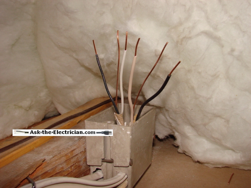
The electrical cable should be installed so that 1 inch of sheathing is inside the electrical box and 6 inches of wire is showing outside of the electrical box.

Step 2: Splice The Ground Wires Together

splicing electrical wires 2 The ground wires must be spliced together in order to maintain the bond of the home electrical ground system. In this fixture box the ground wires are twisted together, then a crimp-sleeve is placed over the wires and crimped tight. The crimp sleeve is placed down over the wires past the half way area.

Step 3: Bond One Ground Wire To The Junction Box

splicing electrical wires 3 After bonding both ground wires together there will be two wires that can be used for the remainder of the ground process. This box has a ground screw and bracket built in so one ground wire is securely fastened under the ground screw.The other ground wire will be available to use once the fixture is ready to hang.

Step 4: Fold The Ground Wires Carefully Back Into The Junction Box

splicing electrical wires 4 Fold the ground wires and push them back into the box keeping the last one out. Straighten out the wires and trim them off evenly if needed, then strip back the insulation about 3/4 of of an inch removing the insulation to prepare the wires for the splice.

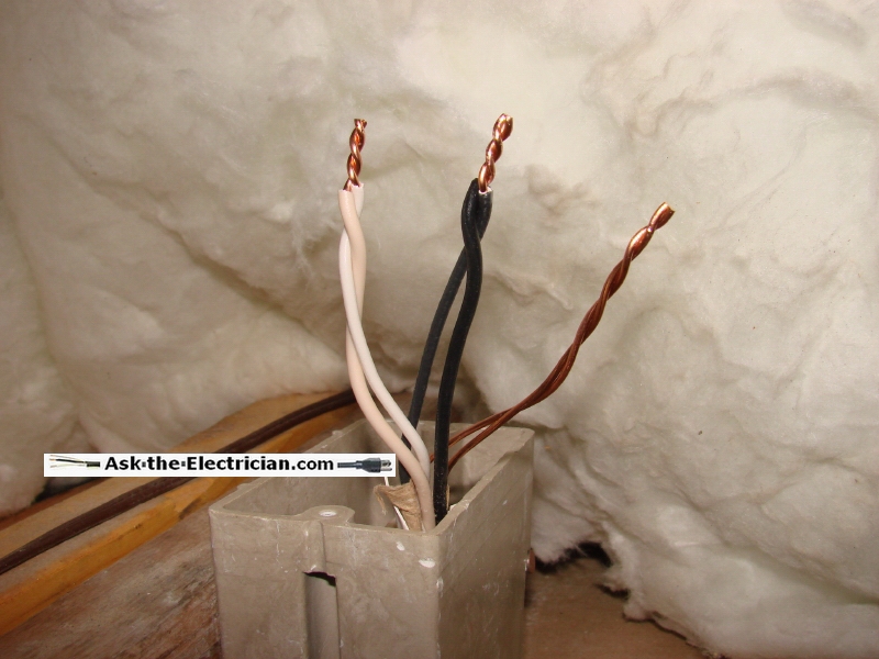
Step 5: Remove The Insulation From The Remaining Wires

splicing electrical wires 5 Use a pair of pliers to twist the bare wire in a clock-wise direction. In this example an additional wire has been added which will be used when installing the light fixture. After twisting the wires together trim the ends evenly to prepare them for the wire connectors. The total length of the bare copper wire area should still be about 3/4 inch.

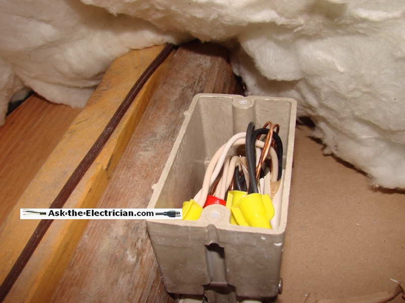
Step 6: Install the Wire Connectors Onto The Twisted Wire Sets

splicing electrical wires 6 Select the right size wire connector, otherwise known as a "wire nut". Screw the splice connector onto the twisted set of wires in a clock-wise direction until each connector is good and snug. The bare wire should be all the way inside the wire connectors. Bare wire should not be seen. If bare wire is seen, back off the wire nut and trim more of the twisted wire sets and reinstall the connector.

Step 7: Fold The Spliced Wires Back Into The Junction Box

splicing electrical wires 7 Fold the spliced wires back into the junction box and pull the remaining lead wires and the ground wire out of the box and then trim off the ends to make them neat and even.

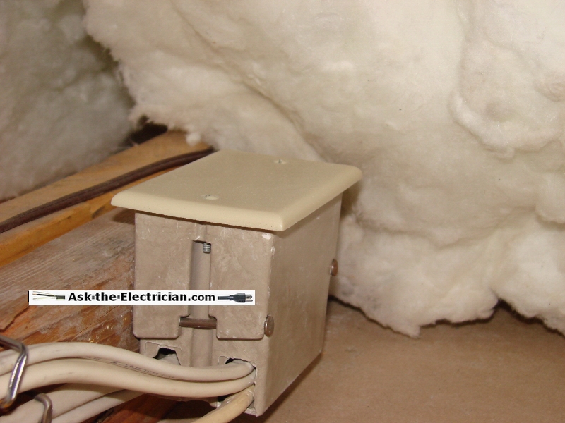
Step 8: Fold The Remaining Wires Into The Junction Box

splicing electrical wires 8 These wires are now ready for a light fixture to be installed. If a device will not be installed then wire connectors would be installed onto the wires that are not connected, and a blank cover would be placed on the junction box. In this project a wall fixture will be installed immediately so the junction box was left open and the wires are ready to attach to the light fixture.

More about Splicing Electrical Wires


Learn more about splicing electrical wires


Home Electrical Wiring

Wire a GFCI Outlet without a Ground Wire

Helping You Wire it Right

NOTE: A List of All my Helpful Videos
Will Display at the End of This Video
So Keep Watching So I Can Help You Wire it Right!

Check out my YouTube Channel:
» AskTheElectrician «
and Subscribe!


Learn more about Home Electrical Wiring
with my online Video Course:
Basic Home Electrical Wiring by Example


» You Can Avoid Costly Mistakes! «
Here's How to Do It:
Wire It Right with the help of my Illustrated Wiring Book

Great for any Home Wiring Project.

  electrical wiring  

See How to Wire it Right!

Learn more about How to Wire Outlets
Complete Guide to Home Electrical Wiring
Perfect for the Homeowner, Handyman,
Electrician and Building Inspector.

Includes:
Methods for Home Electrical Wiring
Wiring Diagrams for Smoke Detectors
Interconnected Smoke Detector Wiring
Wiring Methods for AFCI Circuits
Electrical Codes for Smoke Detectors
....and much more.

» Click here to learn more about Home Electrical Wiring «


Electrical Tips to Help You Wire it Right

The Safest Way to Test Electrical Devices and Identify Electric Wires!

The Non-Contact Electrical Tester
This is a testing tool that I have had in my personal electrical tool pouch for years, and is the first test tool I grab to help identify electrical wiring. It is a Non-contact tester that I use to easily Detect Voltage in Cables, Cords, Circuit Breakers, Lighting Fixtures, Switches, Outlets and Wires. Simply insert the end of the tester into an outlet, lamp socket, or hold the end of the tester against the wire you wish to test. Very handy and easy to use.

The Quickest Way to Check for Faulty Electrical Wiring!

The Plug-In Outlet Tester
This is the first tool I grab to troubleshoot a problem with outlet circuit wiring. This popular tester is also used by most inspectors to test for power and check the polarity of circuit wiring.
It detects probable improper wiring conditions in standard 110-125 VAC outlets Provides 6 probable wiring conditions that are quick and easy to read for ultimate efficiency Lights indicate if wiring is correct and indicator light chart is included Tests standard 3-wire outlets UL Listed Light indicates if wiring is incorrect Very handy and easy to use.

Strip Off Wire Insulation without Nicking and Damaging the Electric Wire!

The Wire Stripper and Wire Cutter
My absolute favorite wire stripping tool that I have had in my personal electrical tool pouch for years, and this is the tool I use to safely strip electrical wires.
This handy tool has multiple uses:
The wire gauges are shown on the side of the tool so you know which slot to use for stripping insulation.
The end of the tool can be used to grip and bend wire which is handy for attaching wire onto the screw terminals of switches and outlets..

The wire stripper will work on both solid and stranded wire. This tool is Very Handy and Easy to Use.

electrical parts

Residential Electrical Parts and Accessories


Light Switches

120volt Outlets

Circuit Breakers

Electrician Tools

Voltage Testers


More about: Splicing electrical wires


Splicing Electrical Wires Safely
Methods for Splicing Electrical Wires
Splicing Electrical Wires For A Power Source
Electrical Circuits for Garage Remodel Wiring
Relocating an Electrical Service Panel
Cut Electrical Cable Causes the Home to Lose Power
What to do with Unused Old Electrical Wiring
Splice Electric Dryer Circuit Wires