Sump Pump and Septic Pump Problems
Electrical Problem: My pump is not working and I am trying to troubleshoot the problem.
- Due to a ground fault interrupt, I’ve lost a circuit.
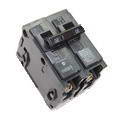
- The electrical panel load center is a GE Power Mark Gold #tm3215ccu.
- Circuit breaker #31 is marked “Panel GFI and outside and sump pump plugs.”
My question:
- Is there an internal GFI reset?
- I’ve reset the breaker with no effect. Or, should I assume that this breaker is shot.
- Unfortunately, I cannot afford an electrician at the moment as we have just bought this house and are up to the neck financially in doing all the stuff needed in a new home.
Thanks for any help you can provide.
Tom
This electrical wiring question came from: Tom, from Minneapolis, Minnesota.
Dave’s Reply:
Thanks for your electrical wiring question Tom.
How to Install and Repair a Sump Pump or Septic Pump
- Application: Install a Sump Pump or Septic Pump.
- Skill Level: Intermediate to Advanced – Best installed by a Licensed Electrician.
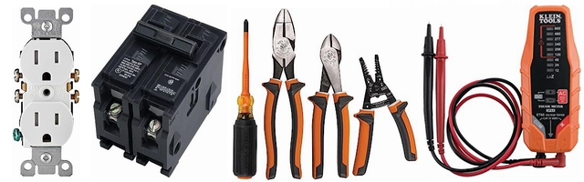
- Tools Required: Basic Electricians Pouch Hand Tools, electric drill, auger bits and extension cord.
- Estimated Time: Depends on personal level experience, ability to work with tools and install electrical circuit wiring.
- Notice: Installing additional outlet wiring should be done with a permit and be inspected.
Example of a Typical Sump Pump or Septic Pump Circuit
A dedicated 120 volt 20 amp GFCI protected circuit. See installation manual for specific details and circuit requirements. Septic pumps typically do not require GFCI protection.
- The GE Power Mark Gold TM3215CCU is a 150 Amp 32-Space 32-Circuit Main Breaker Load Center and sells for around $140.00 at outlets such as Lowe’s or Home Depot. The General Electric GFCI and AFCI circuit breakers are compatible with this top or bottom feed load center.
- Most sump pumps and septic pumps require that the pump and motor are submerged in fluid or liquid and should not be run dry otherwise damage may occur to the unit.
- Some sump pumps and septic pumps may have a built in thermal cut out switch which will automatically shut off the motor if it should over heat, however this will only provide temporary or limited protection.
- All the start and stop components of a septic or sump pump system should be inspected and tested to make sure that they function and are reliable per the design of the specific application.
- When a GFCI trips off this generally indicates that voltage has been detected to ground due to a fault and tests will need to be performed to determine the cause.
- A tripping GFCI circuit typically does not mean that the GFCI device or protection is bad and in need of replacing, but rather that the GFCI device is doing it’s job of detecting a fault that will need to be discovered and repaired.
- In situations such as this it is best to locate a licensed electrical contractor or qualified pump technician in your area who can diagnose and fix the electrical circuit for a sump pump or septic pump.
How to Identify Typical Septic Pump Problems
- Septic System Circuit Power
First check the circuit power for the septic system and make sure it is on and providing circuit power.
- Septic Pump Float Switches
Float switches make the pump turn on either directly or through the septic tank control box.
If one or more float switches become faulty replacement will be required.
Condition of the float switch can be tested by identifying the pair of wires leading to each float and tested with a continuity tester.
Note that some floats are NO or normally open or OFF, and some float are NC or ON. The position of the float will affect the continuity test reading that you receive.
If the tank is full then the START or RUN float should produce a continuity reading.
- Septic Pump Motor
The septic pump motor may have burnt out and require replacement.
A continuity test may be performed on the pump motor to test the motor windings and test power to ground for a short.If the motor is suspected to be OK then the septic pump controller should have a Manual On switch which should bypass the floats and make the pump start.
The pump amperage should be tested to see if the motor is running withing specifications for the horsepower rating of the motor which should be indicated in the owners manual for the septic system or identified inside the septic control box.
IMPORTANT:
- Continuity tests for system components must be performed while the circuit power is OFF.
- Consult the documentation and wiring diagrams of the sump pump or septic pump and the related control system for application specific information.
- Electrical tests and determinations about the septic system are best performed by a licensed electrician or certified septic pump service technician.
More about Installing and Repairing Electrical Circuit Wiring
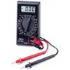
- How to Use Electrical Testers and Voltage Meters
Understanding Digital Volt Meters
- When working on home electrical wiring using voltage meter can play an important part in electrical safety.
- Electrical testers and voltage meters enable you to identify electrical circuits and help prevent the possibility of accidental electrical shock.
Repair Electrical Wiring

-
Troubleshooting and Repairing Electrical Wiring
- Licensed Electrician Reveals the Secrets of Successful Electrical Troubleshooting Methods used to solve the majority of the home electrical problems and wiring failures encountered.
-
More about Home Electrical Wiring
- Basic House Wiring Circuits

-
House Wiring Circuits and Circuit Breakers
- This article looks at common 120 volt and 240 volt house wiring circuits and the circuit breakers that are installed identifying the types and amperage sizes used in most homes.
- Electrical Circuit Breakers
-
Home Electrical Circuit Breakers
- A guide to home electrical circuit breakers and how they work to protect your electrical wiring. When properly installed, your home electrical wiring is protected by a circuit protection device.
- Wiring GFI Outlets
-
GFCI and GFI Wiring Diagrams
- The features and benefits of GFCI outlets and receptacles will give you a clear understanding of the importance why these safety devices are required by code to help protect you and your family against accidental electrical shock hazards.

GFCI Wiring
This list of articles will help you learn about the features and benefits provided by GFI and GFCI Receptacles and how they are wired.
Sump Pump and Septic Pump Problems
Electrical Problem: My pump is not working and I am trying to troubleshoot the problem.
- Due to a ground fault interrupt, I’ve lost a circuit.
- The electrical panel load center is a GE Power Mark Gold #tm3215ccu.
- Circuit breaker #31 is marked “Panel GFI and outside and sump pump plugs.”
My question:
- Is there an internal GFI reset?
- I’ve reset the breaker with no effect. Or, should I assume that this breaker is shot.
- Unfortunately, I cannot afford an electrician at the moment as we have just bought this house and are up to the neck financially in doing all the stuff needed in a new home.
Thanks for any help you can provide.
Tom
This electrical wiring question came from: Tom, from Minneapolis, Minnesota.
Dave’s Reply:
Thanks for your electrical wiring question Tom.
How to Install and Repair a Sump Pump or Septic Pump
- Application: Install a Sump Pump or Septic Pump.
- Skill Level: Intermediate to Advanced – Best installed by a Licensed Electrician.
- Tools Required: Basic Electricians Pouch Hand Tools, electric drill, auger bits and extension cord.
- Estimated Time: Depends on personal level experience, ability to work with tools and install electrical circuit wiring.
- Notice: Installing additional outlet wiring should be done with a permit and be inspected.
Example of a Typical Sump Pump or Septic Pump Circuit
A dedicated 120 volt 20 amp GFCI protected circuit. See installation manual for specific details and circuit requirements. Septic pumps typically do not require GFCI protection.
- The GE Power Mark Gold TM3215CCU is a 150 Amp 32-Space 32-Circuit Main Breaker Load Center and sells for around $140.00 at outlets such as Lowe’s or Home Depot. The General Electric GFCI and AFCI circuit breakers are compatible with this top or bottom feed load center.
- Most sump pumps and septic pumps require that the pump and motor are submerged in fluid or liquid and should not be run dry otherwise damage may occur to the unit.
- Some sump pumps and septic pumps may have a built in thermal cut out switch which will automatically shut off the motor if it should over heat, however this will only provide temporary or limited protection.
- All the start and stop components of a septic or sump pump system should be inspected and tested to make sure that they function and are reliable per the design of the specific application.
- When a GFCI trips off this generally indicates that voltage has been detected to ground due to a fault and tests will need to be performed to determine the cause.
- A tripping GFCI circuit typically does not mean that the GFCI device or protection is bad and in need of replacing, but rather that the GFCI device is doing it’s job of detecting a fault that will need to be discovered and repaired.
- In situations such as this it is best to locate a licensed electrical contractor or qualified pump technician in your area who can diagnose and fix the electrical circuit for a sump pump or septic pump.
How to Identify Typical Septic Pump Problems
- Septic System Circuit Power
First check the circuit power for the septic system and make sure it is on and providing circuit power.
- Septic Pump Float Switches
Float switches make the pump turn on either directly or through the septic tank control box.
If one or more float switches become faulty replacement will be required.
Condition of the float switch can be tested by identifying the pair of wires leading to each float and tested with a continuity tester.
Note that some floats are NO or normally open or OFF, and some float are NC or ON. The position of the float will affect the continuity test reading that you receive.
If the tank is full then the START or RUN float should produce a continuity reading.
- Septic Pump Motor
The septic pump motor may have burnt out and require replacement.
A continuity test may be performed on the pump motor to test the motor windings and test power to ground for a short.If the motor is suspected to be OK then the septic pump controller should have a Manual On switch which should bypass the floats and make the pump start.
The pump amperage should be tested to see if the motor is running withing specifications for the horsepower rating of the motor which should be indicated in the owners manual for the septic system or identified inside the septic control box.
IMPORTANT:
- Continuity tests for system components must be performed while the circuit power is OFF.
- Consult the documentation and wiring diagrams of the sump pump or septic pump and the related control system for application specific information.
- Electrical tests and determinations about the septic system are best performed by a licensed electrician or certified septic pump service technician.
More about Installing and Repairing Electrical Circuit Wiring
- How to Use Electrical Testers and Voltage Meters
Understanding Digital Volt Meters
- When working on home electrical wiring using voltage meter can play an important part in electrical safety.
- Electrical testers and voltage meters enable you to identify electrical circuits and help prevent the possibility of accidental electrical shock.
Repair Electrical Wiring
-
Troubleshooting and Repairing Electrical Wiring
- Licensed Electrician Reveals the Secrets of Successful Electrical Troubleshooting Methods used to solve the majority of the home electrical problems and wiring failures encountered.
-
More about Home Electrical Wiring
- Basic House Wiring Circuits
-
House Wiring Circuits and Circuit Breakers
- This article looks at common 120 volt and 240 volt house wiring circuits and the circuit breakers that are installed identifying the types and amperage sizes used in most homes.
- Electrical Circuit Breakers
-
Home Electrical Circuit Breakers
- A guide to home electrical circuit breakers and how they work to protect your electrical wiring. When properly installed, your home electrical wiring is protected by a circuit protection device.
- Wiring GFI Outlets
-
GFCI and GFI Wiring Diagrams
- The features and benefits of GFCI outlets and receptacles will give you a clear understanding of the importance why these safety devices are required by code to help protect you and your family against accidental electrical shock hazards.
GFCI Wiring
This list of articles will help you learn about the features and benefits provided by GFI and GFCI Receptacles and how they are wired.
Wire Size for a Sump Pump Circuit
[ad#block]Electrical Question #1: I plan to put a separate circuit in for the sump pump in my septic system.
- I have a Rigid 1/2 horse pump (10.5 amp motor) and will be using a 20 amp breaker.
- The wire I have on hand is 14 gauge.
- Is this an adequate wire, or do I need to get a larger gauge?
This electrical wiring question came from Duane, a Homeowner from Ravenna, Ohio.
Electrical Question #2: Is a sump pump in a basement required to be on a GFCI Outlet?
- Should a sump pump in a basement be protected by a GFCI outlet?
This electrical wiring question came from Joseph in Baltimore, Maryland.
Dave’s Reply:
Thank you for your electrical questions.
Electrical Wiring for a Sump Pump Circuit
- The wire size that should be used for the 20 amp septic sump pump circuit should be #12 gauge.
- The sump pump should be protected by either a GFCI outlet or a GFCI circuit breaker.
- A means of disconnect for the sump pump must be located within sight and readily accessible.
- If a receptacle outlet will be installed then a weather proof cover must be installed to offer protection from the weather even while the sump pump is plugged in.
More about Sump Pump and GFI Wiring
GFCI Wiring

GFI Outlet Wiring
This list of articles will help you learn about the features and benefits provided by GFI and GFCI Receptacles and how they are wired.

Electric Circuit Listing
The size of the home electrical service panel is designed by calculating the square footage of the home and factoring in the code requirements for the electrical circuits that are required.
Circuit breaker
Electrical Wiring Protection using Circuit Breakers
- A guide to home electrical circuit breakers and how they work to protect your electrical wiring.
- When properly installed, your home electrical wiring is protected by a circuit protection device.
For more information about Circuit Wiring
Circuit Wiring

Electrical Circuit Wiring
This article looks at common 120 volt and 240 volt house wiring circuits and the circuit breakers that are installed identifying the types and amperage sizes used in most homes.
Wire Size for a Sump Pump Circuit
[ad#block]Electrical Question #1: I plan to put a separate circuit in for the sump pump in my septic system.
- I have a Rigid 1/2 horse pump (10.5 amp motor) and will be using a 20 amp breaker.
- The wire I have on hand is 14 gauge.
- Is this an adequate wire, or do I need to get a larger gauge?
This electrical wiring question came from Duane, a Homeowner from Ravenna, Ohio.
Electrical Question #2: Is a sump pump in a basement required to be on a GFCI Outlet?
- Should a sump pump in a basement be protected by a GFCI outlet?
This electrical wiring question came from Joseph in Baltimore, Maryland.
Dave’s Reply:
Thank you for your electrical questions.
Electrical Wiring for a Sump Pump Circuit
- The wire size that should be used for the 20 amp septic sump pump circuit should be #12 gauge.
- The sump pump should be protected by either a GFCI outlet or a GFCI circuit breaker.
- A means of disconnect for the sump pump must be located within sight and readily accessible.
- If a receptacle outlet will be installed then a weather proof cover must be installed to offer protection from the weather even while the sump pump is plugged in.
More about Sump Pump and GFI Wiring
GFCI Wiring
GFI Outlet Wiring
This list of articles will help you learn about the features and benefits provided by GFI and GFCI Receptacles and how they are wired.
Electric Circuit Listing
The size of the home electrical service panel is designed by calculating the square footage of the home and factoring in the code requirements for the electrical circuits that are required.
Circuit breaker
Electrical Wiring Protection using Circuit Breakers
- A guide to home electrical circuit breakers and how they work to protect your electrical wiring.
- When properly installed, your home electrical wiring is protected by a circuit protection device.
For more information about Circuit Wiring
Circuit Wiring
Electrical Circuit Wiring
This article looks at common 120 volt and 240 volt house wiring circuits and the circuit breakers that are installed identifying the types and amperage sizes used in most homes.
Should You Share the Sump Pump Circuit?
Can I plug a mini refrigerator into a GFCI outlet that has my Sump Pump?
- Or does the sump pump require a dedicated outlet?
This electrical question came from: Sean, a Homeowner in Pennsylvania.
Dave’s Reply:
Thanks for your electrical question Sean.
Sump Pump Circuit Requirements
- If the sump pump is responsible for preventing an area from flooding then it would be best to have a dedicated circuit for it, and I would not plug anything else into it.
- A similar example that we can compare this to would be a septic system. In my area of California, new installations of septic systems require two separate circuits, one for the septic pump and the other for the high level alarm circuit.
- The design here is to be able to have a high level alarm if the septic pump or the pump circuit should fail. There are exceptions where you may have only one dedicated circuit which provides power to a septic system controller provided the controller has two circuit breakers which provide separate branches of power for the septic pump and the high level alarm system.
- Considering both of these devices, the refrigerator and the sump pump, I think you would agree that it would be best if the refrigerator was plugged into a separate source of power.
Electrical Tip for Sump Pumps – Avoid a Possible Problem Beforehand
- It is good to consider all the possibilities of failure that could occur and deal with them right away and put into place all the safe guards to make sure the project is done right the first time and prevent problems later on.
- One such safeguard is to make sure that all sump pumps are protected by GFCI, either at the outlet or the circuit breaker that provides power to the sump pump.
The Following will assist you with your Sump Pump Electrical Wiring:


- Wiring Electrical Outlet for the Home
- Home electrical wiring includes 110 volt outlets and 220 volt outlets and receptacles which are common place in every home. See how wiring electrical outlets for the home are done.
- For more information about Electrical Safety
- Electrical Safety

- Home Electrical Safety
- A new approach to keep kids and electricity apart with hopes to prevent children from being injured by electricity.
Should You Share the Sump Pump Circuit?
Can I plug a mini refrigerator into a GFCI outlet that has my Sump Pump?
- Or does the sump pump require a dedicated outlet?
This electrical question came from: Sean, a Homeowner in Pennsylvania.
Dave’s Reply:
Thanks for your electrical question Sean.
Sump Pump Circuit Requirements
- If the sump pump is responsible for preventing an area from flooding then it would be best to have a dedicated circuit for it, and I would not plug anything else into it.
- A similar example that we can compare this to would be a septic system. In my area of California, new installations of septic systems require two separate circuits, one for the septic pump and the other for the high level alarm circuit.
- The design here is to be able to have a high level alarm if the septic pump or the pump circuit should fail. There are exceptions where you may have only one dedicated circuit which provides power to a septic system controller provided the controller has two circuit breakers which provide separate branches of power for the septic pump and the high level alarm system.
- Considering both of these devices, the refrigerator and the sump pump, I think you would agree that it would be best if the refrigerator was plugged into a separate source of power.
Electrical Tip for Sump Pumps – Avoid a Possible Problem Beforehand
- It is good to consider all the possibilities of failure that could occur and deal with them right away and put into place all the safe guards to make sure the project is done right the first time and prevent problems later on.
- One such safeguard is to make sure that all sump pumps are protected by GFCI, either at the outlet or the circuit breaker that provides power to the sump pump.
The Following will assist you with your Sump Pump Electrical Wiring:
- Wiring Electrical Outlet for the Home
- Home electrical wiring includes 110 volt outlets and 220 volt outlets and receptacles which are common place in every home. See how wiring electrical outlets for the home are done.
- For more information about Electrical Safety
- Electrical Safety
- Home Electrical Safety
- A new approach to keep kids and electricity apart with hopes to prevent children from being injured by electricity.
More about: Sump pump circuit
Sump Pump Circuit Wiring
Fix an Electrical Circuit for a Sump Pump or Septic Pump
Sump Pumps and Dedicated Circuit Outlets
Wiring Methods for Adding Kitchen Circuits
Wiring a Receptacle for a Lift Pump for a Septic System
Controlling a Pump and Monitoring Energy Consumption
Repair a Tripping GFCI Outlet
Preventing Basement Water Damage or Flood
|