


» How to Wire a Wall Receptacle Outlet
» Need Electrical Help? Ask the Electrician
Switch Outlet Wiring Diagrams

|
Summary: This switched outlet electrical wiring diagram shows two scenarios of wiring for a typical half hot outlet that can be used to control a table or floor lamp.
© By: Dave Rongey |
Understanding Switched Outlet Wiring for Home Electrical Applications
The switched outlet wiring configurations show two different wiring scenarios which are most commonly used.
The wiring and connections will depend on where the power enters the circuit. The connections for a switched outlet also known as a Half Hot Plug.
The diagram shows the power entering into the circuit at the switch box location, then sending one power line for the outlet which is hot all the time and a switched leg for the top half of the outlet being used for a table lamp or a floor fixture
InstructionsSwitched Outlet Electrical Wiring Diagram #1 |
| The Electrical Power Source Enters at the Switch |
 |
Outlet Wiring for a Table Lamp or a Floor Light Fixture
These electrical wiring diagrams show typical connections.
The diagram below shows the power entering the circuit at the grounded outlet box location, then sending power up to the switch and a switched leg back down to the outlet.
Notice that these outlets have the tab removed from the "hot" side or Brass side of the outlet which allows the top half of the plug to be controlled only from the switch while the bottom end of the outlet remains "hot" all the time. This is shown in the pictures below.
Switched Outlet Wiring Diagram #2 - Power Source Enters at the Outlet |
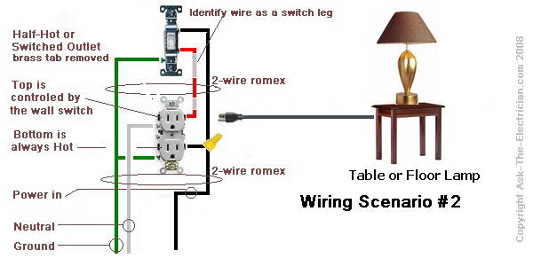 |

Switched Outlet Wiring VariationsThe switch I am replacing has two red wires plugged into the back and two black wires plugged into the one below. If I want to keep the same set up I can just connect the two red wires to the top brass screw and the two black wires to the bottom but must break the small brass tab between the screws not the plastic, correct? If I don't care to use the wall switch all I have to do is to cap off the red and connect one black wire to one brass screw and one to the other brass screw without removing the brass tab, correct? From what you have described, I believe that you are correct. The brass tab can be left in place if you no longer want half of the outlet to be controlled by the switch. More About How to Wire a Switched Outlet
Learn more about Wiring a Switched Outlet |


