When it comes to household electricity, there is a lot more to consider than simply turning a switch On or Off. Within these articles you will find some of the most common questions homeowners ask about switches. Once you understand the different types of switches and outlets and follow a wiring diagram you should be able to install a new electrical wiring in your home or repair existing problems with light switches and outlets.
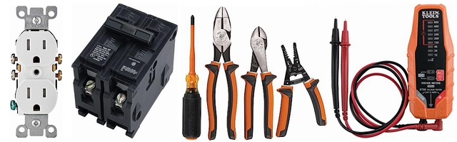
Here are some of the more common configurations for switches and outlets.
After learning the following information you will be able to wire switches just as well as the pros.
Home Electrical Wiring Diagrams
Featuring diagrams for the most common electrical devices used in the home
Diagrams for Wiring Switches
- Single Switch
- 3 Way Switch
- 4 Way Switch
- Dimmer Switches
Diagrams for Wiring 120 Volt Outlets
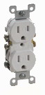
- Wall Receptacle Outlet
- GFCI Outlet
- AFCI Outlet
- Switch Controlled Outlets
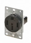
Diagrams for Wiring 240 Volt Outlets
- Clothes Dryer Outlet
- Kitchen Range Outlet
Electrical Wire Colors
|
Electrical switch diagrams that are in color have an advantage over ones that are black and white only. *The individual wires on the diagram should be colored the same as the actual wires you will be using. Green or bare wire is the ground wire. White wire or off-white is neutral. The neutral wire carries power back to the service panel. Black wire indicates the hot wire. The hot wire carries power from the panel to the device you are wiring. Red wire blue, or other colors also indicate hot wires. *Important Note: When wires or cables such as Romex are used with switching applications and as Switch Legs, the function of a colored wire may be different from what is noted here. The only way to positively identify wires used for any application is to purchase a good volt tester and understand how to use it . See more about the types of wire and what they are used for.More about Home Electrical Wire More about Electrical Testers |

Electrical Wiring Symbols
When looking at any switch diagram, start by familiarizing yourself with the symbols that are being used.
The electrical symbols will not only show where something is to be installed, but what type of device is being installed. Make sure you understand the symbols on your diagram before beginning your project.
There should be a chart on your diagram showing what the different symbols being used represent, much like a legend on a map.
More about Electrical Home ImprovementsResidential Wiring Diagrams and Blueprints

Wiring Diagrams
A surface ceiling light will be shown by one symbol, a recessed ceiling light will have a different symbol, and a surface fluorescent light will have another symbol. Each type of switch will have a different symbol and so will the various outlets. You will even find symbols showing the location of smoke detectors, your doorbell chime, and the thermostat.
More about Wiring Diagrams and Symbols
![]()
Switch Wiring Diagrams
A single switch provides switching from one location only. “Single-Pole” may sound simple, but there are different ways to wire a Single-Pole Switch. The power can come from either the switch box or the fixture box and a set of electrical switch wiring diagrams will explain each of these scenarios to you clearly.More about Wiring Diagrams for Switches

3-Way Switch Diagrams
- 3-Way Switches are used to control one or more fixtures from two different locations. This is a common configuration in hallways and staircases.
- There are many ways to wire a 3-Way Switch. The power can start at a fixture or either of the two switches. Without a switch-wiring-diagram it can be very easy to make a serious mistake that will cause the circuit to malfunction and possibly become a hazard.

4-Way Electrical Switches
- One of the most complicated wiring configurations is a 4-Way Switch. These switches enable you to control one or more fixtures from three or more locations. It would be almost impossible to write the instructions in a way that you could simply read them and complete your project without these wiring diagrams.
- The wiring diagrams that I have prepared will make it possible for you to successfully wire one or more 4-Way Switches.
- Did you know you can have any number of 4-way switches installed on one light circuit? Once you see how these switches are wired you'll be amazed. As you will see, its just one more step up from the 3-way switch configuration.

3-Way Dimmer Switch Diagram
- A dimmer switch can be either a rotary or a sliding switch that lets you adjust the intensity of a light. Both are wired the same way.
- What a great way to enjoy softer light and a reduced energy bill!

Diagrams for Switches
As important as wiring diagrams are to the successful completion of your wiring project, safety and respect for electricity are essential.- Never work on live circuits. Before you begin your project, identify the circuit you’reworking on and then turn off power to that circuit at the main panel.
- Then confirm that the power is off with a voltage tester.
IMPORTANT:
If at any time you feel unsure about what you are doing, please call a licensed electrical contractor.
110 Volt Outlets
- Standard wall outlet are typically easy to replace and wire, however it may be discovered that the wiring is not correct or that the outlet is not grounded and will require further attention. Wiring diagrams and instructions will assist you with these situations.
- Switched outlets are very popular and typically found in bedrooms and living rooms where they are used to control floor lamps or table lamps. Existing outlets may be converted to provide the desired functionality for most any room.
- The key elements for these wiring scenarios are describer with wiring diagrams and instructions. Kitchen garbage disposals are typically plugged into an outlet under the sink which is typically controlled by a countertop switch. the disposal outlet or switch may require replacing or a remodel project may require wiring to be installed for a new disposal outlet. Outlet diagrams instructions and diagrams will help with your project.
- GFI Outlets or GFCI Outlets are required in areas of the home and often they may need to be replaced or an older home upgrade project will require installing GFCI protected outlets.
- The wiring of these devices can be tricky so I have devoted a section describing several methods for wiring GFCI Outlets and GFCI Receptacles.
220 Volt Outlets
- Electric clothes dryers may have a 3-wire or 4-wire cord or 220 volt outlet configuration requiring special attention to the connections as found in the instructions and diagrams.
- The kitchen electric range may also be found to have a 3-wire or 4-wire cord or 220 volt outlet which will require proper electrical connections and wiring as found in the diagrams and instructions.
- Most Arc Welders require a dedicated electrical circuit and 220 volt outlet that is sized according to the specifications of the welder as described in further information.
More about How to Wire 220Volt Outlets