


More about Wiring Switches
Learn more about wiring switches |
» Home Electrical Wiring
» Electrical Wiring Directory
» Wiring Diagrams for Light Switches
» Need Electrical Help? Ask the Electrician
» Wiring Diagrams for Light Switches
» Need Electrical Help? Ask the Electrician
Wiring Diagrams for Light Switches

|
Summary: Fully explained wiring diagrams and photos show how to wire switches including: single switches, 3-way switches, 4-way switches, and dimmer switches. © By: Dave Rongey |
Diagrams for Wiring Light Switches
Before wiring a light switch please consider the following:
Make sure the circuit power has been turned off, and mark the circuit breaker or fuse to indicate that work is being done.
Make sure the switch is correct for your application. The switch should be rated for the circuit voltage and the amperage. For example: A standard light switch in the USA for a bedroom is typically rated for 120 volts, 15 amps.
Before replacing a light switch, make sure to identify the existing wiring before removing the wires. Make a note describing how the wires are connected to the switch. Create a drawing and mark the wires with electrical tape or masking tape. If possible, take a picture of the wiring inside the switch box, and how the wires are attached to the switch.
Single Switch Wiring Diagram 1Easy to Understand Light Switch Wiring - Fully Explained Light Switch Wiring with Diagrams and Pictures with Step-By-Step Instructions to Guide You. |
|
Single Switch Wiring Diagram 2Fully explained pictures and wiring diagrams about wiring light switches describing the most common switches with photo diagram 2. |
|
 |
3 Way Switch Wiring Diagram Part 13Way Switch Wiring Diagrams #1, #2 and #3The key to three way switch wiring depends on two main factors. These wiring diagrams help you identify the power feed and the switch leg leading to the fixture. |
|
3 Way Switch Wiring Diagram Part 23Way Switch Wiring Diagrams #4, #5 and #6Continuing on with wiring three way switches, these next three wiring diagrams in this series will help you identify three more possibilities for wiring the power feed and the switch wiring that leads to the light fixture.. |
 |
4 Way Switch Wiring DiagramsFully explained 4 way switch diagrams. 4-way switches are a convenient way to operate lighting fixtures from three or more locations. The electrical wiring adds additional wiring to the same principles of 3-way switching. |
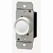 |
Wiring Dimmer SwitchesFully Explained Wiring for 3 Way Dimmer Switches with Wiring Diagrams and Pictures - Instructions about How to Wire 3 Way Dimmer Switches. |


